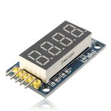
2Pcs 4 Bits Digital Tube LED Display Module Board With Clock
₹340.92
A part of the review has been auto-translated.

I wasn't a fan of the code I found for it so decided to write my own Ardunio library. Writing your own library is the best way to understanding how it works. I have posted information and the code here. https://monotok.org/arduino-using-c-to-write-7-segment-4-bit-display-driver/

Send 16-bit word serial messages for the two 74hc595 controllers. High byte = segments ".gfedcba" active low. Lowest 4 bits of low byte selects digit(s) to display. High 4 bits = don't care Send bit 15 first, bit 0 last. Clock each data bit on DIO with a positive SCLK edge. After 16 bits are clocked in, latch with a positive edge on RCLK. If daisy-chaining, 16 bits per module, then RCLK edge. Proceed to next digit. Look at avg 5ms per digit or less, to give a steady display. RCLK and SCLK only cares about rising edges, not levels. Typically, you will lower RCLK at start of a word, place a bit on DIO and then give SCLK a high pulse. When all 16 bits are done - raise RCLK again. Adjust for number of segments. A "1" will be much brighter than a "8" with same delay. 1ms per displayed segment in a digit is a good starting value. Example: write 12.34 word0: 11111001 00001000 ; segments "1", digit 3, no decimal point, delay=2ms word1: 00100100 00000100 ; segments "2", digit 2, with decimal point, delay=6ms word2: 10110000 00000010 ; segments "3", digit 1, no decimal point, delay=5ms word3: 10011001 00000001 ; segments "4", digit 0, no decimal point, delay=4ms For small microcontrollers, I suggest lookup tables for both segment encoding and delay. Add one to delay if decimal point is used on that digit.
This was easy enough to get working with the code posted in other reviews, but that code needed some tweaking and lacked a function to print 4-digit decimal values (the original only had one for hex). I went ahead and made the edits necessary to get up and running a little quicker.. https://goo.gl/nYzghE Cheers!
Super utile dans de nombreux projets nécessitant un afficheur 7 segment comme un voltmètre ou un ampèremètre !!! Le rapport qualité/prix est excellent. Si vous trouvez moins cher, contactez moi ;) Just so AMAZING EDIT: Update link with sketch demo code for Arduino Uno - http://www.vcc2gnd.com/2014/08/8-digit-numeric-display-module-with_4.html Thanks for this code & for the blog post
After a long wait I received 2 dead modules, wish they would let me give zer0 stars!
Good assortment of hard to find stuff . Fast shipping too.
Nice little 4x seven segment led board, useful for projects such as time or temperature display.
Very goodly.
The shipping was slower than the expected delivery time.
This is so much easier to use and wire than the standard 3461BS. Comes in handy on so many projects.